A force can push an object along. It can also make an object turn, and how well it does that depends on more than its size. Push a door near its hinges and it barely moves; push at the handle and it swings. Push the handle straight toward the hinges and nothing happens at all. The quantity that captures all of this is torque.
Where and which way you push
Think about the door from above. The hinge is the axis. Three things decide how strongly a push turns the door:
- how hard you push (the force F);
- how far from the hinge you push (the distance r);
- which way you push (the angle θ between the door and the force).
Only the part of the force at right angles to the door does any turning. A push along the door, toward or away from the hinge, just squeezes or stretches the door against the hinge.
Line of action and lever arm
Extend the force arrow into a long straight line in both directions. This is the force's line of action. Now measure the shortest distance from the axis to that line, the distance at right angles to it. This is the lever arm, r⊥.
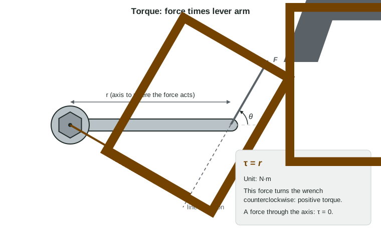
The torque is the force times its lever arm:
τ = r⊥F = rF sin θ
The two forms say the same thing, since r⊥ = r sin θ. Torque is measured in newton-meters, N·m. When the force is perpendicular to r (θ = 90°), sin θ = 1 and τ = rF. When the line of action passes through the axis, r⊥ = 0 and the torque is zero, however big the force.
Worked example 1. A cyclist pushes on a pedal crank 0.17 m long with a 300 N force at 40° to the crank. What torque does she exert about the crank's axle?
Principle: τ = rF sin θ, with θ the angle between the crank (r) and the force.
τ = (0.17 m)(300 N)(sin 40°) = (0.17)(300)(0.643) N·m = 33 N·m.
The lever arm is (0.17 m)(0.643) = 0.11 m. Using cos 40° here (which gives 39 N·m) is a common slip: check which angle you have.
The sign of a torque
A torque tends to turn an object either clockwise or counterclockwise. On this exam you describe its direction just that way, never with a vector arrow. Choose one direction as positive, usually counterclockwise, and give each torque a sign. The net torque is the sum of the torques with their signs.
A quick way to find a sign: imagine the object pinned at the axis and only that one force acting. Which way would it start to turn? A force pushing down to the left of a pivot turns a bar counterclockwise; the same force to the right of the pivot turns it clockwise.
Worked example 2. A light bar turns on an axle at its center. A 12 N force pushes down 0.50 m left of the axle, an 18 N force pushes down 0.25 m right of it, and an 8.0 N force pulls up 0.40 m left of it. Counterclockwise is positive. What is the net torque?
12 N: down on the left, counterclockwise: +(0.50 m)(12 N) = +6.0 N·m.
18 N: down on the right, clockwise: −(0.25 m)(18 N) = −4.5 N·m.
8.0 N: up on the left, clockwise: −(0.40 m)(8.0 N) = −3.2 N·m.
τnet = 6.0 − 4.5 − 3.2 = −1.7 N·m, clockwise. A bar at rest would start turning clockwise, even though the largest single torque is counterclockwise.
Force diagrams
A free-body diagram puts every force at one dot. That is fine for asking how the center of mass accelerates, but it hides where each force acts, and torque depends on exactly that. So for rotation you draw a force diagram: sketch the object (a bar, a door, a beam), and start each force arrow at the point where that force acts.
The rules are the same as for any free-body diagram. Draw only real forces, each labeled with its type and agent ("FN, pivot on beam", "Fg, Earth on beam", "FT, cable on beam"). Draw whole forces, not components. Never add a "net torque" arrow. A uniform object's weight acts at its center.
Common slips
| Slip | Fix |
|---|---|
| Using the distance to the point of application as the lever arm, whatever the force's direction | Use r⊥ = r sin θ, the perpendicular distance to the line of action |
| Using cos θ | θ is the angle between r and F; the turning part is F sin θ |
| Adding all torques as positive | Give each a sign: counterclockwise + and clockwise − |
| Reading a spring scale as a torque | A scale measures force; torque needs the lever arm too |
Scaling is direct: at the same angle, doubling the force or doubling r doubles the torque. Halving the force while doubling r leaves the torque unchanged, which is why a longer wrench makes a stuck bolt easier.